Consultation

Odd‑form component insertion machine

High precision and high adaptability; High flexibility; Data‑driven production and process reliability assurance.
High Precision
High Flexibility
High Stability
Full‑Scenario Digitalization

Product Introduction

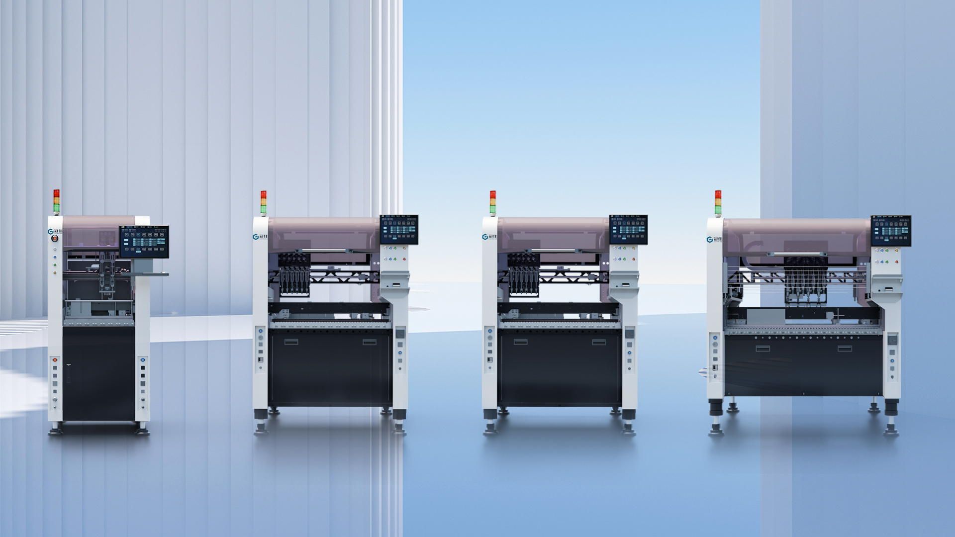
Odd‑Form Precision Inserter (full name: Automatic Odd‑Form Electronic Component Inserter) is a high‑end automation equipment in the field of Through‑Hole Technology (THT). It is specifically designed to automatically insert irregularly shaped, larger electronic components that cannot be handled by standard tape‑and‑reel packaging or surface‑mount (SMT) placement machines into designated through‑holes of a printed circuit board (PCB) with extremely high precision and speed, preparing the board for subsequent wave soldering or selective soldering.

It serves as the automated bridge between standard SMT placement and manual assembly/soldering, solving the automation challenge of placing “non‑standard” components in PCB assembly. It is a key enabler for achieving fully automated PCB assembly.

Product Features

  • High positioning accuracy
    Repeat positioning accuracy of ±0.02mm ensures high precision in assembly and manufacturing quality.
  • High-speed motion
    Fast axis movement and excellent acceleration significantly improve production efficiency.
  • High stability
    High-quality components and advanced control algorithms ensure long-term stable operation.
  • Modular design
    Modular and standardized design ensures high precision in assembly and manufacturing quality.
  • Smart sensing
    Supports vision guidance and force‑control sensing for intelligent operation and assembly.
  • Smart connectivity
    Supports industrial Ethernet and multiple communication protocols for easy integration into smart factory systems.

Function Introduction

Function Items

Modular feeder design
High-precision machine vision positioning
Precision drive structure
Multi‑function pick‑up head
Multiple independent grippers

Function Description

Supports various feeding methods including bulk material (vibratory bowl), tape & reel, tube, and tray. Feeders are modular and interchangeable, enabling high changeover efficiency.
Typically employs dual industrial cameras or multiple vision systems (top vision, bottom alignment vision, side vision). Top vision is used for PCB Mark point positioning and CAD data compensation; bottom vision is used to inspect component lead position, coplanarity, and polarity; side vision is used to check lead condition.
Utilizes an XYZ high-speed precision closed-loop servo system or linear motor drive, combined with high-precision ball screws and guide rails, to achieve fast and smooth motion.
Equipped with both pneumatic gripper and vacuum suction nozzle, with automatic switching based on component characteristics.
Typically equipped with 4 to 8 independently actuated grippers, each capable of independent Z‑axis lifting and R‑axis rotation to accommodate different component insertion angles and depths.


Application Scenarios